Eight Advantages of Vacuum Conveying: A Breath of Fresh Air
In the vast realm of material handling, vacuum conveying is amongst the top options available. ...
De Dietrich Process Systems is experienced in designing waste treatment systems that qualitatively meet process requirements for:

Effective technology for water purification
PolyAluminum Chloride production is one of the most exigent processes for glass-lined equipment due to its high corrosive and abrasive effect. The glass-lined reactor is a critical component of the PAC process.
The PAC synthesis occurs under high pressure and high temperature. PolyAluminium Chloride is the product of the batch reaction between solid Aluminium Hydroxide [AL(OH)3] and liquid Hydrochloric acid (HCI).
DDPS has supplied hundreds of glass-lined reactors for PAC production over the past 30 years, acquiring a thorough understanding of PAC process requirements and characteristics. We have developed specific solutions for the PAC reactor to handle the highly corrosive and abrasive process:


Waste water cleaning, product recovery, minimum energy consumption
The combination of extraction and distillation permits a low energy consuming recovery of valuable products from process waste water streams.
Industrial waste water often contains high boiling solvents, such as phenol or dichlorobenzene, preventing it from being discharged into a sewage treatment plant without reprocessing and cleaning. Since destruction through burning is a bad alternative for ecological and cost reasons, the preferred way is phenol recovery with simultaneous cleaning of the waste water. Phenol is the example used to describe the method preferred by DDPS. The phenol content, which depends on the process, is normally 2-12%. The low phenol concentrations eliminate separation by distillation, in which the water is evaporated out, due to the high energy requirements. Here, extraction offers the decisive advantage. Methylisobutylketone (MIBK), an extracting agent, removes phenol from the waste water in the extraction column K1. The charged extracting agent is cleaned again in the distillation column K2 and returned to the bottom of the extraction. The phenol accumulates in the bottom of the subsequent rectification (column K2) and can be used again in production.
While the waste water flowing out of the extraction K1 may be free of phenol, it carries along traces of the extracting agent, which are recovered in the stripper K3. The MIBK/water azeotrope accumulates at the head of the column, where it is separated in the separator B1 into the light MIBK phase and the heavy water phase. Since the distillation column K2 is operated without water, indirect heating is planned here, while direct steam can be introduced into the stripper.
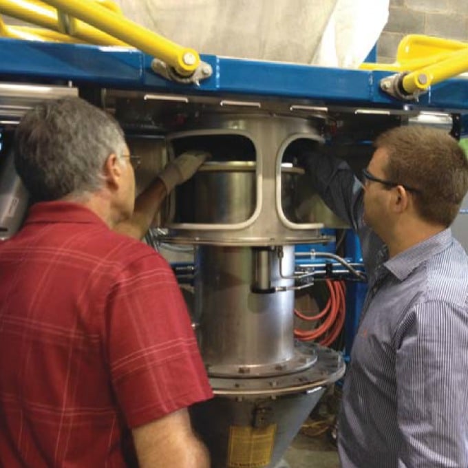
Fig. 1: Sieve plate extraction column and distillation column
18 in. diameter column

Fig. 2: Phenol recovery flow sheet

The planned heat recovery in the waste water stream and the use of dephlegmators make the overall process energetically favorable and appropriate for the ecological requirements applicable today. With phenol content in the waste water of less than 5 ppm, the water can be discharged into the biological sewage treatment plant. The extracting agent circulates and is not consumed to a noticeable extent. The recovered phenol can be used again in the process.
Fig. 3: Head vessel of extraction column

Phenol waste water accumulates in many areas of plastic and resin production and in the production of alkylated phenols. The waste water volumes to be processed range from 0.5 m³/h up to 10 m³/h, whereby the chosen extraction unit depends on the waste water volume and the attendant material. With greater volume streams, extraction is performed continuously in serially connected mixer-settlers, since the technical effort is then more favorable than with the pulsed sieve plate column.
The system shown in the illustrations processes waste water stream of 4 m³/h. In this case, we have chosen a pulsated sieve plate 16 in. diameter column with 105 plates for the extraction. The 20 in./18 in. diameter distillation column with ordered packing works at a pressure of 0.3 bar abs. The waste water with the phenol removed, lightly overheated via a flash tank, and enters the 18 in. diameter stripper. The scope of supply contained the system with measurement and control devices, vacuum generator, vessels and receivers and the performance run with original product. The special difficulty with every waste water cleaning lies in the attendant materials, whose effects on the main process can be critical. The feed can contain suspended matter, cresols, acetone, formaldehyde or methanol. In the system shown, suspended matter collects in the extraction head and must be continuously fed out. Cresols crystallize at low temperatures so that, when auxiliary heating is lacking and the pipeline layout is unsuitable, a blockage of the system through solids must be feared. The lightly volatile solvent acetone, methanol and formaldehyde, which the waste water also contains, could be removed by means of a preceding stripper. Experience with the built systems has shown that it is precisely the investigation of secondary materials in our test facility that contributes to an optimal system concept.

Maximum removal of acetic acid from water, recovery of other organic side products, minimum content of organics in waste water, minimum energy consumption
Acetic acid is the most widely used aliphatic carbonic acid. Apart from its use as a reaction partner during the production of acetic-acid esters, it is also frequently employed as a solvent, for instance, during the production of cellulose acetate or during the manufacture of pharmaceutical products. In most cases its recovery is of great economic significance.
Separation of the acetic acid and water mixture by rectification is not economically viable since this mixture has a very small thermal separation factor. This would require a high rectification column with a huge number of separation stages which would have to be operated with a high reflux ratio, requiring high energy and operating expenses.
Azeotropic rectification is a more feasable solution that operates either with or without the extraction stage, depending on the respective acetic-acid concentration. The addition of an auxiliary substance means that the volatility of the water is increased, which in turn means that separation can be achieved with lower energy consumption. In the case of acetic-acid concentrations of below 40 wt%, the acetic acid is initially extracted from the aqueous solution with a suitable extraction agent, before pure recovery occurs during the rectification of the azeotropic mixture.
The recovery method using extraction must be taken into consideration, regardless of the concentration, if supplementary impurities in the initial mixture, like salts, would be likely to cause problems during direct recovery by distillation. This method deals with the recovery of acetic acid by means of liquid-liquid extraction and downstream azeotropic rectification.
Fig. 2: Liquid/vapor equilibrium

Normally, more low boiling extraction agents are used. Characteristics like solubility in water, absorption capacity, distribution coefficient, price, availability and composition of the azeotrope, and requirements in terms of environmental and health protection must be taken into account for the purpose of this selection.
Table 1 shows a selection of extraction agents suitable for the recovery of acetic acid, with details on the average distribution coefficient between the organic and aqueous phase, density of the extraction agent at 20°C; enthalpy of vaporization and boiling point temperature of the extraction agent; and the proportion of water and temperature of the binary azeotrope between extraction agent and water. The average distribution coefficients do not differ from one another. As a result, all the extraction agents listed here must be regarded as practically equivalent with regard to the extraction. The economic viability of the overall process greatly depends on the energy requirements of the solvent rectification, which in turn depends on the reflux ratio and thus on the performance of condenser and evaporator.
The difference in boiling temperatures between the pure acetic acid (118°C) and the azeotropic point provides clue on the size of the reflux ratio. According to this, the reflux ratio in the case of all the extraction agents listed here ought to be in the same order of magnitude. The energy consumption, however, also depends on the vaporisation enthalpy of the azeotropic mixture, which in turn is determined by the proportion of water in the azeotrope. Thus the energy consumption in the case of the use of EtAc or MTBE as extraction agents ought to be the lowest. It can be shown that these observations only apply up to certain feed concentrations of acetic acid, which, for example, amount to approx. 15 wt% in the case of ethyl acetate and MTBE. If the feed concentrations are higher, then the quantity of extraction agent must be increased in accordance with the balance and vapor-liquid equilibrium, which consequently causes an increase in the operating costs.
A more favorable alternative in terms of energy is the QVF method described below. By means of appropriate process principle, economic working of the entire procedure can be achieved, even with high inflow concentrations of acetic acid. It can be gathered from the liquid-liquid equilibrium for the two preferred ternary systems (see figs. 3 and 4) that if ethyl acetate is used, there is considerable reciprocal solubility with water. The space in the immiscibility gap is relatively small, so that feed concentration of 30 wt% should not be exceeded for safe extraction work. On the other hand, the immiscibility gap in the case of the MTBE / acetic-acid / water system is more pronounced, and the reciprocal solubility lower. Feed mixtures with acetic-acid concentrations of up to around 40 wt% can, therefore, be reprocessed without problem using MTBE as the extraction agent.
Fig. 3: Equilibrium diagram of the MTBE/acetic-acid/water system
(information in wt% at 20°C).

Fig. 4: Equilibrium diagram of the ethyl-acetate/acetic-acid/water system
(information in wt% at 20°C).

Table 1: Extraction agents for the separation of acetic acid from effluent

Fig. 5 shows the flow chart of a conventional extraction plant for the recovery of acetic acid. It consists of the extraction tower, the rectification tower for the recovery of the extraction agent, and the water-stripping tower. As a rule, the feed mixture has a greater density than the solvent, and is fed in at the top end of the extraction tower. Inside the tower it streams towards the bottom and in the process gives off acetic acid to the extraction agent. Depending on the effort, residual concentrations of 0.1-0.5 wt% can be achieved. Since the aqueous phase is simultaneously saturated with the extraction agent in the extraction tower, it is recovered in a downstream stripping tower. It can in this respect be performed with live steam. The extraction agent accumulate at the top end of the rectification tower and the acetic acid at the bottom of the tower resulting in acetic-acid concentrations of practically 100 wt%. If there is a risk of any higher-boiling components also passing into the organic phase during extraction, then it is recommended that the acetic acid should be discharged in vapor form.
Fig. 5: Flow chart of the classical process

Fig. 6: Flow chart of the QVF process

Fig. 6 shows the flow chart of the QVF process. Here, similar to the conventional method, acetic acid is also extracted during the extraction stage from the process water with the aid of a suitable extraction agent (MTBE in most cases). The extraction tower, however, is operated in such a way that a high a concentration as possible of acetic acid is achieved during the extraction-sequence phase with simultaneous fulfilment of the required raffinate purity. During this operation the extracted phase contains a high proportion of acetic acid and, consequently, also water. In the downstream rectification stage, separation of the extracted phase now occurs in an azeotropic mixture consisting of extraction agent and water, and in acetic acid of the required concentration. The excess water present in the extracted phase is distilled as a liquid side-stream in the rectifying section of the rectification tower. A particularly favorable choice of the draw off point and reflux ratio can result in a composition in the side stream, which approximately corresponds to that of the process water. After cooling to the operating temperature of the extract phase, the side stream is guided back into the extraction tower. The position of the feeding point depends on the concentration of the acetic acid in the side stream.
The costs of the whole process are determined by the costs for the separation of the extraction agent from the acetic acid. Meticulous care is therefore necessary both in terms of the design and layout of the control system of this process stage. In the case of the classical process with ethyl acetate or MTBE as extraction agents, separation can occur without problems. Nevertheless it should be taken into account that in the tower a ratio of ethyl acetate to water is set at which the separating factor relative to acetic acid is at its greatest. This is potentially very simple if the inlet concentration of acetic acid in the process water is below 15 wt%. In the case of the QVF process the rectification step is also unproblematic. Nevertheless, the control system of the tower is more expensive by comparison with the conventional method, i.e. a certain concentration profile must be adjusted in the tower with a distinctive concentration maximum for water.
In addition the flow rate of the side stream must be controlled. The automatic control-technology concept developed by QVF for this purpose has already proven outstandingly good in practical applications.
Greater expenditure in the case of the QVF process is justified by the up to 40% lower energy requirement by comparison with the classical process. This saving in energy results from the low extraction agent main stream. As a result, high acetic-acid concentrations develop in the extract, so that the proportion of water in the extract is also higher than in the case of the classical process. However, this excess water is drawn off as a liquid side from the rectification tower. As a result, it is possible to achieve azeotropic composition in the distillate, and then only the quantity of water contained therein has to be condensed in the top end of the tower. It is not possible to make any generally applicable statements on the operating costs of acetic-acid recovery, since these depend on the inflow concentration of the acetic acid, run-off concentrations of the products, type of extraction agent, choice of method variations, and heat recovery etc. For the purpose of the assessment two (sets of) reference values are given below for each method. The figures apply to the use of MTBE, and assume that 99 wt% liquid boiling acetic acid is being distilled at the bottom of the rectification (tower).
The duty of the evaporator for the classical process amounts to the following:
The following values have been calculated for the QVF process:
In many cases the process water contains low boiling components like ethanol or acetone, which must be removed along with the acetic acid. Using MTBE as an extraction agent, this can be performed as follows. During the steady-state operation the low boiling components pass the extraction tower without being extracted and reach a downstream stripper, which is equipped with a rectifying section (see fig. 7).
In the stripper section of the tower the water is cleared of the extraction agent and accompanying components. On the other hand, the rectifying section of the tower is used to separate MTBE from the accompanying components. However, during the separation of components, which have a small boiling-temperature difference to MTBE (e.g. acetone), MTBE losses can be expected. In this case it is possible to resort to another variation in the process. For this purpose a water stripper without rectifying section is used. Nevertheless, the stripper is operated in such a way that the accompanying components are driven to the bottom of the tower and the extraction agent driven to the top of the tower. In this case, however, it is necessary for the loaded aqueous phase to be purified, for example, by a biological treatment.
Fig. 7: Stripper with the additional draw off for accompanying components

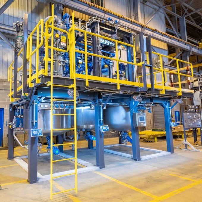
Fig. 8: Extraction Unit

DE DIETRICH PROCESS SYSTEMS is the leading global provider of Process Equipment, Engineered Systems and Process Solutions for the fine chemical, chemical and pharmaceutical industry.
Quick Links