There are multiple options available for overhead arrangements, and the one you select is dependent on your process objectives. Vessel overheads are suitable for various processes, including:
· Boiling under reflux
· Distillation
· Hydrodistillation
· Rectification
The selection, layout, and sizing of the condenser for a batch operation is a very detailed procedure when all the parameters are defined. Here we’ll focus on condenser sizing procedures based upon the size of the glass or glass-lined steel reactor. This is a useful tool for initial equipment sizing prior to final process design.
Energy Balance Overview:
In the overall heat balance, we can simplify the heat duty required by the condenser by ignoring the heat loses (reactor should be insulated), and distillate subcooling, which will be performed by a secondary heat exchanger:
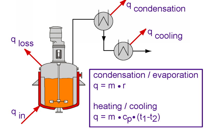
Thus, our condenser duty is equal to our reactor’s heat input:
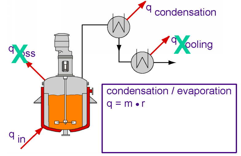
Setting Q rxtr (evaporation only) = Q cond, gives
A jkt x ΔTLM x U rxtr = A cond x ΔTLM cond x U cond,
Solving for A cond = (A jkt x ΔTLM x U rxtr)
(ΔTLM cond x U cond)
We factor out ΔTLM, by assuming the jacket temperature difference will be about ½ of the reactors due to a smaller difference in utilities to bubble point temperatures & rise in coolant thru the condenser.
And, the U values for typical applications of glass/glass-lined steel reactors and condensers are:
· Glass-Lined Steel Reactor - 70 BTU/hr-ft2-F (steam heating)
· Glass Coil - 50 BTU/hr-ft2-F (water cooling/organic vapors)
· Glass Shell & Tube - 70-100 BTU/hr-ft2-F
· SiC Shell & Tube - 160-370 BTU/hr-ft2-F
This provides us with: A cond = A jkt x 2 x (Urxtr/Ucond)
and for:
Glass Coil HX: 2.8 x A rxtr jkt (which we round to 3 x A rxtr jkt)
Glass Shell & Tube HX: 2 to 1.4 (which we round to 1 to 2 x A rxtr jkt)
SiC Shell & Tube HX: 0.9 to 0.4 (which we round to 0.5 to 1.0 x A rxtr jkt)
The following chart is a handy reference to use to when sizing a condenser. It lists the estimation for the maximum evaporation rate based on heat exchanger type, as described above:
Heat Exchanger Type Factor x Vessel Heating Area (ft2)
Coil type 1.5-3
Shell and Tube (glass tubes) 1-2
Shell and Tube (SiC tubes) 0.5-1
The low factor applies to atmospheric pressure and a solvent of high boiling point. For vacuum and a low boiling point, the higher factor must be used.
Again, this is a very preliminary sizing to aid in initial scoping. Detailed questionnaires on condenser / heat exchanger sizing are available to further develop your overheads.