 Moving solids from one place to another can present a variety of challenges in any process. Because there is no solution that fits every operational requirement, it’s essential that some preliminary research be done to determine what solution is the best fit for your application. That’s why DDPS created a comparison guide - to help you navigate through the various mechanical and pneumatic conveying options available. This guide defines and compares some of the most widely used conveying technologies to help you make an informed choice. This post will provide a high-level overview, but we recommend downloading the guide to get a more in-depth evaluation of the different solutions available.
Mechanical Conveyors
Mechanical conveying is a method of transferring product from one place to another via physical mediums or apparatuses such as screws, chains/cables, and discs. Three of the most popular mechanical conveyor designs used in industrial applications are:
Flexible Screw Conveyors
In this design, the screw (also referred to as a helix, spiral, or auger) rotates inside of a plastic tube which is often made of Ultra High Molecular Weight Polyethylene (UHMWPE). This material of construction, in combination with the hollow screw design, allows for “bending” of the conveyor, which enables it to be installed at various angles. Rigid metal piping may also be used as tubing for materials that are more abrasive or corrosive. The screws themselves have various cross-sectional profiles (round, flat, or flat with beveled edges) and are selected based on the properties of the product. A variable frequency drive (VFD) motor starter can be used to control the screw’s rotation speed and fine tune the discharge rate from the conveyor.
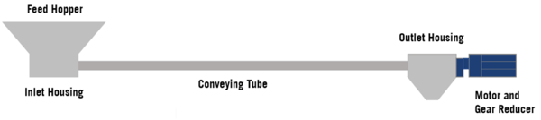
Fig. 1 – Typical configuration of a flexible screw conveyor
Tubular Drag Conveyors
Mechanical conveyors of this type can be installed in multiple planes as a single continuous system. The system consists primarily of a stranded steel cable or chain with polyethylene discs, a conveying tube or pipe, drive housing and idler housing(s). In some cases, when transferring to more than one location, multiple discharge housings can be installed along the tubular routing. The cable, chain, or discs used can vary based on the equipment design and requirements of the operation. UHMWPE discs are often used, but there are also cases such as high temperature or corrosive environments, in which metal discs are necessary.
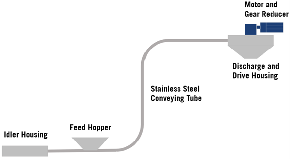
Fig. 2 – Typical configuration of a tubular drag conveyor
Aero-Mechanical Conveyors
An aero-mechanical conveyor is very similar to a tubular cable drag conveyor. The biggest difference is the speed. An aero-mechanical conveyor can operate up to 10 times faster than a tubular cable drag conveyor. Moving material at such an elevated speed requires a few design considerations. First, when making 90-degree bends, this type of conveyor requires idler or sprocket housings instead of long-radius elbows. Additionally, since the conveyor moves at a high speed, product characteristics must be considered. Due to the higher velocity, powders tend to transfer better in aero-mechanical conveyors, and materials that need to maintain their shape and size are generally not well-suited for this type system.
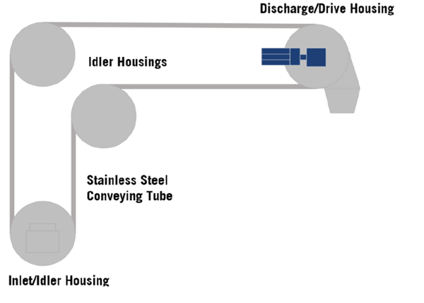
Fig. 3 – Typical configuration of an aero-mechanical conveyor
Pneumatic Conveying
Pneumatic conveying systems are commonly used to transfer bulk solids such as powders, flakes, granules, or prills from one point to another through an enclosed conveying line. They generally consist of four basic elements: an air source, a material feed device, a convey line, and an air-solids separator.
Pneumatic conveyors are typically divided into two primary categories:
Dilute Phase Conveyors
Dilute phase systems operate with relatively high gas stream velocities which exceed the “saltation velocity” of the material. Saltation velocity is the minimum gas velocity required to entrain the solid particles in the gas stream and allow them to be carried along in suspension. When the gas velocity is reduced below the conveyed material’s saltation velocity, solid particles will begin to drop out of suspension. However, they will often continue to move along the bottom of the conveying line more slowly due to friction with the gas stream and particles that remain suspended. Almost any material can be conveyed in dilute phase. However, the high gas velocities required can negatively impact long-term operational expenses.
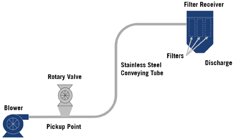
Fig. 4 – Typical configuration of a dilute phase conveyor
Dense Phase Conveyors
Many materials can be conveyed at much lower velocities with dense phase conveying. This typically occurs in two common modes. The first is “moving bed” or “dune flow” and the second is “plug flow.” In dune flow, the material tends to move along the bottom of the conveying line in wave-like forms that do not fully fill the conveying line. In plug flow, the solids are conveyed as full-bore plugs in the transfer line, with gaps of air between them. Whether or not a material can be conveyed in dense phase depends upon several physical properties including particle size, shape, size distribution, and density, but the most important properties are its air permeability and air retention, which are also commonly referred to as aeration and fluidization.
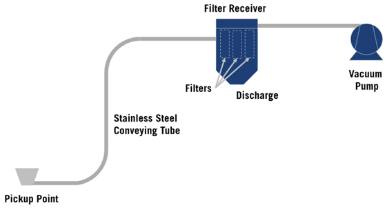
Fig. 5 – Typical configuration of a dense phase conveyor
Because every material has unique characteristics and properties, and every process has distinct objectives, no standard transfer system is suitable for every application. Most conveyor manufacturers will combine off-the-shelf components to design a custom or semi-custom system to meet a customer’s specific process requirements. When evaluating your conveying system options, the best advice is to thoroughly evaluate your materials, along with the transfer rate and distances required by the application.
Our comparison guide on Mechanical vs. Pneumatic Conveying gives a more detailed look at the technologies and the equipment types highlighted in this post. For a complete overview, as well as the advantages and limitations of each type system, including a side-by-side ranking on criteria such as reliability, distance, flow rate, and more, download your copy today.