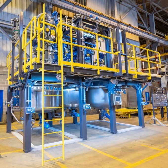
Absorption of Hydrogen Chloride

Absorption_of_HCl

Processes to purify waste gases or to produce aqueous concentrated hydrochloric acid

Hydrogen chloride gas is generated as a by-product or waste gas by a variety of processes within the chemical industries. In many countries there are strict maximum emission levels for hydrogen chloride, mandating that it be removed from waste gas streams. This may be done simply by scrubbing hydrochloric acid out of the waste gas, or where the concentration is high enough, absorbing HCl to produce hydrochloric acid as a product.

Hydrogen chloride has a great affinity for water and the absorption can be easily accomplished as long as a suitable method is found to contact the gas and the water. The absorption of hydrogen chloride into water generates a great deal of heat which has to be removed from the system. The theoretical maximum concentration achievable is dependent on the temperature and the partial pressure of HCI in the exhaust gas entering the plant.

The most appropriate HCI absorption process for any particular application depends on the nature of the feedstock and on the product required. The three basic types are batch-operated HCI scrubbers, continuously operated adiabatic absorbers, and continuous isothermal absorbers.

Hydrogen chloride and hydrochloric acid are very corrosive materials and will attack many materials of construction commonly used in the chemical process industries. Borosilicate glass is the ideal material of construction, being suitable for handling hydrogen chloride gas, hydrochloric acid, and any impurities present (with the exception of hydrofluoric acid).

HCl Scrubber with and without Neutralization

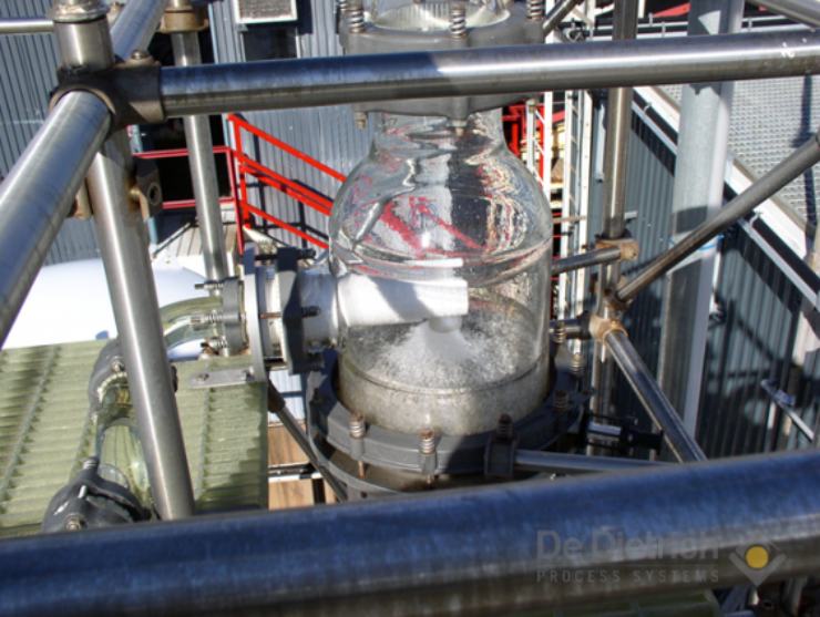
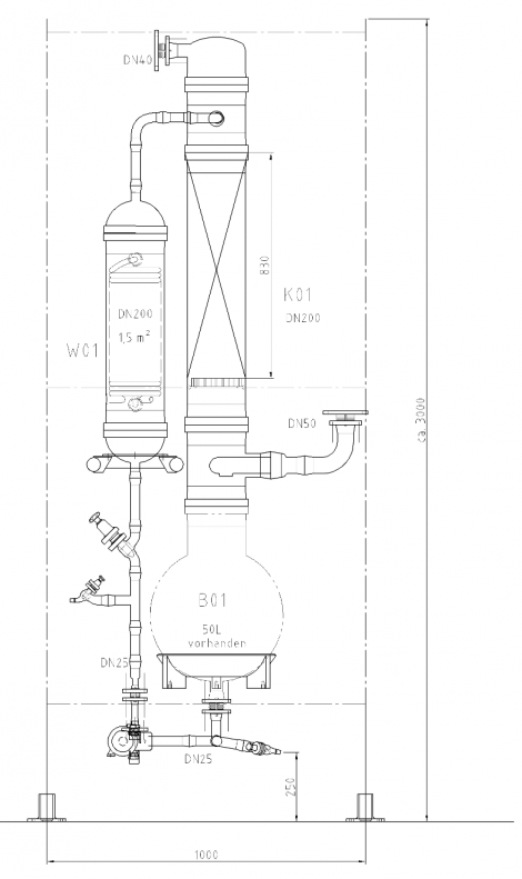
The HCl gas scrubber represents the simplest form of an HCI absorber operating continuously with respect to the gas flow and batch-wise with respect to the absorbing liquid. This appartus is useful for applications where the concentration of the hydrogen chloride is low and further processing to form hydrochloric acid has no economic advantage. The aim is to remove the HCl from waste gas streams. In this type of unit the liquid to gas ratio in the column is usually very high. Any heat of solution generated in the process will therefore be taken up by the liquid phase, thus avoiding the need for coolers.

Increased concentration or increased total amount of HCl in the gas stream may require to remove the generated heat. Removal of the heat is done by a cooler placed in the recirculation loop. The addition of sodium hydroxide to the absorption liquid neutralizes absorbed HCl, improving mass transfer and providing a more efficient scrubbing process. To achieve this, a vessel with a pump are placed at the based of the column where the neutralizing absorption liquid is stored. This liquid is circulated through the column, continuously absorbing HCl gas until the absorbing liquid becomes semi-batch wise neutralized. This can be monitored by continuous pH measurement.

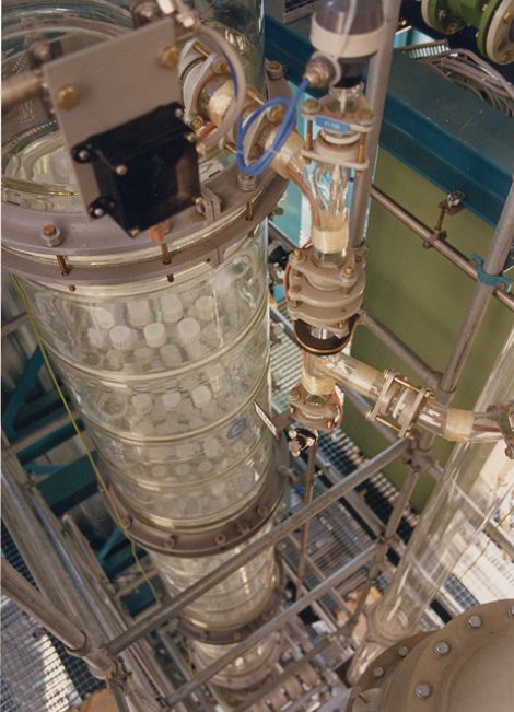
HCl-Scrubber DN200

HCl Scrubber DN200

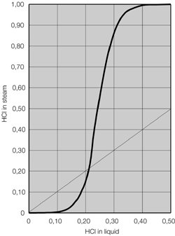
Boiling point of hydrochloric acid as function of the HCl-concentration

DroppedUriImg-6maxh=272,maxw=250,h=272,w=250

Absorption of HCl in Water

The absorption of hydrogen chloride in water is strongly exothermic ~2100 kJ/kg HCl, which means that the absorption liquid easily becomes warm. High concentrations of HCl in water can be achieved only at temperatures lower than 40°C (104°F) . In order to keep these low temperatures, the removal of absorption energy is necessary. This removal is done in different ways, as further described in isothermal and adiabatic HCl-absorption.

Request More Information

Isothermal Absorption of Hydrogen Chloride

Boiling point as a function of HCl-concentration in the liquid phase

DroppedUriImg-6maxh=272,maxw=250,h=272,w=250

The preferred process to produce concentrated hydrochloric acid

The absorption process of HCl is called isothermal when the absorption heat is withdrawn along the absorption process. This means that supplementary cooling devices are installed along the absorption column or a falling film absorption unit is used instead of a column. The absorption process is then carried out at lower temperatures. This enables a higher concentration of acid in the liquid compared to adiabatic absorption process.

Falling Film Absorber

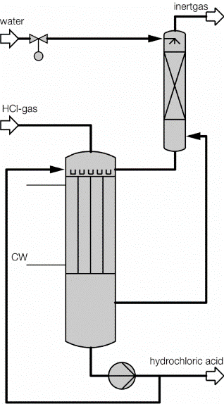
Hydrogen chloride feed gas enters at the top of the falling film absorber and flows co-currently with weak acid coming from the tails tower. The heat that is released from the solution as a result of the absorption process is removed by the cooling water flowing in the shell side of the falling film unit.

Product acid at up to 38% hydrochloric acid leaves at the bottom of the falling film absorber at a suitable temperature for storage and is ready for pumping.

The remaining unabsorbed hydrogen chloride gas and any inert gases present leave at the bottom of the falling film unit and enter at the bottom of the tails tower. Process feed water entering at the top of the tails tower absorbs the hydrogen chloride to form dilute hydrochloric acid. The dilute acid flows by gravity to the top of the falling film absorber to serve as the liquid feed to the tubes.

The QVF falling-film-absorber is a fully corrosion-resistant apparatus. Its special design features ensure that an even fluid distribution is achieved on the tube side.

Packed Column with Cooling Loops

An alternative to the falling film evaporator is a column with a condenser and two additional cooling loops, as shown in the diagram below.  For the upper cooling loop, the liquid reflux is withdrawn and pumped through a heat exchanger.  The feed of the lower cooling loop is the bottom final product itself.

Falling film absorption unit

falling film absorption unit

Request More Information

Adiabatic Absorption of Hydrogen Chloride

Preferred process if maximum concentration of HCl in the liquid phase is not the target

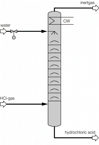
These absorbers, as their name implies, operate without any heat removal from the reaction zone. In the process, hydrogen chloride gas is easily and quantitively absorbed by fresh water flowing down the column. The maximum possible gas flow for a given column diameter depends basically upon the type of packing material in the column. The minimum flow rate of feed water is reached when an unpermissible amount of HCl is leaving the column at the gas outlet.

Adiabatically operated HCl-absorption column

adiabatically operated HCl absorption column

Bubble cap tray column for waste air cleaning

Bubble cap tray column for waste air cleaning

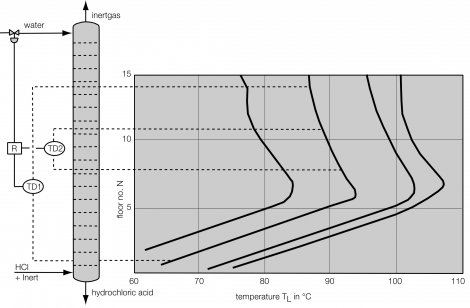
Depending on the amount of absorbed HCl, the generated dissolving heat may vaporize water which rises to the head of the column with any other non-soluble components of the gas stream. They are condensed and refluxed together with the absorption water. The major part of the generated dissolving heat is removed by this condensation process hence outside the absorption process.  If the condensation process occurs, the temperature downwards along the column is defined by the boiling point of the acid and will increase downward along the column up to a maximum value where the azeotropic concentration is reached. From there the temperature decreases again further downwards to the outlet of the column with increasing HCl concentration. This temperature profile along the column can be used to control the liquid feed flow for a maximum absorption efficiency as illustrated on the following scheme. This scheme shows the temperature profiles for different amounts of inert gases. The right curve represents the situation for a feed gas without inert gases.

Temperature profile along an adiabatic HCl-absorption column

Temperature profile along an adiabatic HCl-absorption column

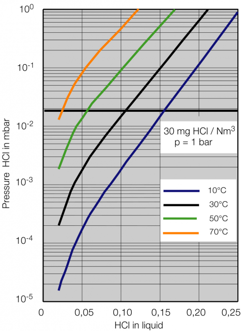
HCl Partial pressure as a function of HCl-content in the liquid phase

HCl Partial pressure as a function of HCl-content in the liquid phase

Achievable Acid Concentration

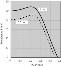
The concentration of the HCl in the liquid outlet depends on the overall water/HCl ratio but cannot be higher than the solubility of HCl in water at a given temperature. Therefore, the maximum achievable acid concentration in the liquid outlet flow depends on the temperature of the liquid acid at the bottom of the column. The lower the temperature is at this outlet point, the higher the maximum achievable concentration of HCl in water. This temperature is determined by the boiling point of the aqueous HCl solution at the bottom of the column. The boiling point is a function of the HCl-content at the bottom which is at a given pressure a result of the ratio of the HCl containing feed gas and the absorption water.

Adiabatic absorbers produce, under normal operating conditions, hydrochloric acid of 30-31% strength. This compares with a theoretical maximum of 35% under such operating conditions.

The water content in the feed gas has an impact on the overall water to HCl ratio and hence on the maximum achievable HCl concentration. The lower the H2O-content in the feed gas the higher is the maximum achievable HCl concentration in the liquid acid due to the resulting mass balance.

Process Systems Questionnaire

Request More Information

Cleaning of HCl 

Hydrochloric acid may occur as gaseous or aqueuous effluent or product from different sources. Even fresh procured HCl of technical grade may not meet the specification for a dedicated process. There are many cases where cleaning or purifying hydrochloric acid becomes advantageous or necessary. The majority of contaminations in hydrochloric acid are from the following:

  • Other hydrogen halogens such as HF, HBr or HI
  • Other gases less soluble in aqueous HCl (e.g. SO2 or NOx)
  • Non-volatile inorganic materials such as mineral salts (e.g. halogenides)
  • Volatile and non-volatile organic components

The cost to remove these contaminations should be as low as possible. This is especially achievable when combining cleaning steps with other process steps in one single unit.

Separation of Non-Volatile Contaminations

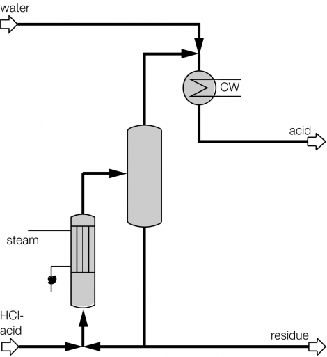
Non-volatile material contained in hydrochloric acid, such as heavy metal salts, are held back simply by evaporating the acid. A suitable layout scheme is presented below. Upon existence of metal halides, the evaporated hydrochloric acid will contain parts of the corresponding hydrogen halides. The metal salts remain in the residue.

Cleaning of HCl by evaporation

Cleaning of HCl by evaporation

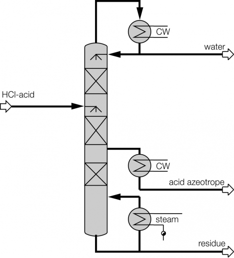
Cleaning by rectification

Cleaning by rectification

Another design option combines an evaporator with a rectification column to facilitate a gaseous withdrawal above the lowest packing. This way a waste HCl mixture can be split into water, azeotropic hydrochloric acid and higher boiling components such as HNO3. This is especially interesting if a pre-concentrationing step is necessary for the overall process anyway.  Here, the concentration is combined with the cleaning process.

Separation of Organic Materials and Absorbed Gases

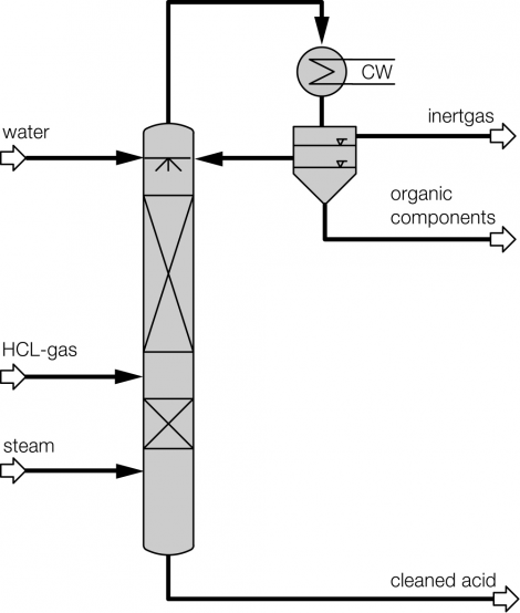
In case the incoming HCl waste gas stream also contains volatile components which are less soluble in water than HCl, they can be stripped off in the same column. Examples are gases like SO2 or organic substances which are either light boiling like acetone or non-misible in water like toluene for example. HCl is absorbed in the upper part of the column, increasing the temperature. Additional steam is introduced from the bottom part of the column stripping off the organic material.  The uprising vapors are then condensed. If these vapors contain noncondensible gaseous contaminations like SO2 it can be an uprising condenser whereas a falling condenser is more appropriate for condensible contaminations avoiding the immediate reflux of the condensate back into the column and enabling an optional phase separation.

Separation of Organics

Separation of Organics

 Separation of bromine

Separation of Bromine

Removal of Bromide Ions

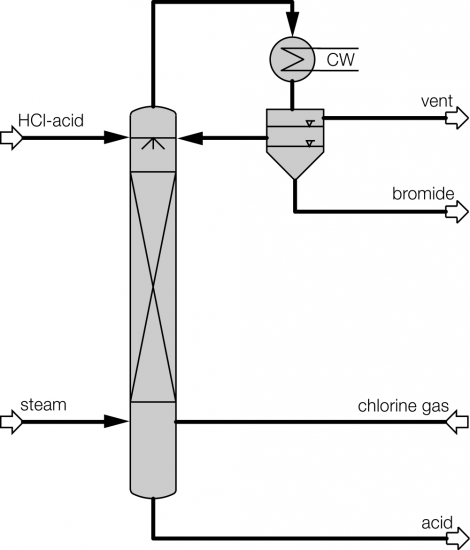
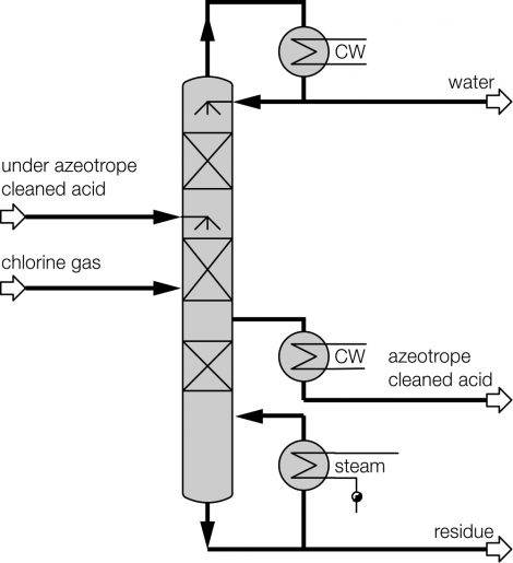
As the natural sources of chlorides also contain bromides, hydrochloric acid may also include hydrobromic acid.  Depending on the amount of bromides, the target is either the removal or recovery of bromine. The bases of the removal of the bromides is their oxidation to volatile bromine which can be stripped off. The most commonly used oxidizing agent is chlorine.

The debromination requires, as described above, a stripping process which can be combined with a pre-concentration of the hydrochloric acid to produce azeotropic acid as shown here.

Removal of bromides combined with HCl pre-concentration

Removal of bromides combined with HCl pre-concentration

Separation of Fluoride Ions

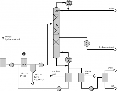
The presence of flourides in hydrochloric acid can be unfavorable for the further use of the product and is especially disadvantageous when using equipment made of borosilicate glass or glass-lined steel. The removal of flourides is simplified by the fact that CaF2 has a very low solubility and CaCl2 has a very high solubility in aqueous HCl. Accordingly, by the addition of Ca-salts like CaO to flouride containing aqueous HCl, the flourides are precipitated as CaF2 and can be separated from the acidic suspension. The Ca containing hydrochloric acid is then fed to a rectification column as described above so that gaseous azeotropic hydrochloric acid can be withdrawn above the evaporator. The residue containing Ca-salts is partially fed back to the precipitator and partially withdrawn from the system. The Ca-loss is compensated by the addition of CaO. The higher the amount of Ca in the precipitator, the lower the remaining flouride concentration is, which can be reduced down to very low values. This patented QVF process simplifies the removal of fluoride ions from hydrochloric acid, so that cleaned hydrochloric acid can be forwarded for further industrial use.

QVF Process to Separate Fluoride Ions from Hydrochloric Acid

QVF process to separate fluoride ions from HCl

Process Systems Questionnaire

Request More Information

Concentration of HCl Acid above Azeotropic Point

This azeotrope exist at a boiling temperature of 108.6°C, system pressure of 1 bar and a HCl concentration of 20.2wt%.

If the acid concentration is lower than the azeotrope mixture, the acid can be concentrated only up to the azeotropic point. Further concentration needs special procedures.

Basically, some technologies may be considered:

  • Dual-pressure technology (variation of system pressure)
  • Extractive rectification technology (addition of an extractive agent)
  • Combination of both technologies

All technologies can also be used for the production of HCl gas.

Dual-pressure Technology

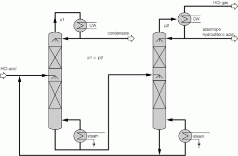
The location of the azeotrope point is contingent to pressure. Therefore, it is possible to achieve full separation due to rectification by employing two different pressures. The principle of dual-pressure technology is presented in illustration 1.

At first, the mixture is treated by rectification at low pressure (vacuum/standard pressure), so that a mixture of azeotrope composition is produced. Then the mixture is further rectified in a second column at high pressure (standard pressure/over-pressure). An azeotrope mixture results at the bottom outlet in the second column, yet whose concentration is lower than the azeotrope composition of the first column due to the system pressure. Thus, the bottom product of the second column may be recycled back to the first column. Concentrated hydrochloric acid of the desired concentration level is produced at the head of the second column.

Within the pressure range from 100 mbar to about 3 bar, the composition change to the azeotropic point is marginal. Dual-pressure technology for HCl acid concentration above the azeotropic point is therefore generally considered to be less economical in that pressure range.

Illustr. 1: Dual-pressure technology

dual pressure technology

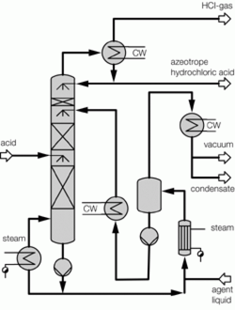
Illustr. 2: Extractive rectification technology

extractive rectification technolgy

Extractive Rectification Technology

A more economical technology is the extractive rectification technology (see illustration 2). Employing this technology, whereby the azeotrope point is to be suppressed as best as possible, increases the relative volatility of HCl. The relative volatility may be impacted by change of the activity coefficients. This is achieved by addition of a third ingredient, the extractive agent, which displays strong hygroscopic properties. Hydrochloric acid of high concentration or optionally HCl gas may be produced at the head of the extractive rectification column upon choice of an appropriate extraction agent. In the column the extraction agent is diluted with water, which is extracted in a selective fashion from the inflowing mixture. Subsequently, the extractive agent is recycled and fed into the extractive rectification process.

Extractive agent

An appropriate extractive agent must display the following physical properties. The agent:

  • must increase the relative volatility of HCl towards water.
  • should be soluble with the components of the feed acid throughout the whole concentration range.
  • should display a high boiling point relative to the components of the feed acid, and
  • should lend to separation under economic conditions for energy consumption in order to regenerate from water.

Sulfuric acid and aqueous solutions with metal chlorides, such as MgCl2 and CaCl2 are appropriate extraction agents for the concentrationing of hydrochloric acid. Generally, concentrated CaCl2 solutions are deployed due to availability reasons. They also aid in the recycling, concentration, and cleaning of hydrochloric acid.

The phase equilibrium of the material system CaCl2/HCl/H2O is of decisive importance for the design of the extractive rectification technology. One must especially consider that the components do not behave in an ideal fashion within the fluid phase, and display electrolytic behavior. In order to reduce the thermal load of the column material in the best lowest fashion, extractive rectification procedures are generally performed by employing low vacuum status.

Combined technology for cleaning and concentration

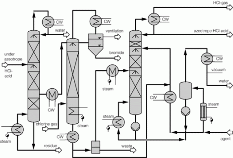
It is of decisive importance that the inflow contains the least amount of water content for the extractive rectification process in order to enhance the effectivity of the rectification process. This is achieved in a combined technology process by pre-concentration of the absorbed acid. Independent of the absorption concentration, the hydrochloric acid is forwarded to the extractive rectification process on an azeotropic level. Thus, a lower amount of extraction agent is sufficient due to the higher HCl concentration level of the feed flow. In the course, the circulation for extraction agent may be designed smaller, compared to contemporary technologies for the recycling of HCl from smoke gases. Illustration 3 displays such a combined technology, which is comprised of preliminary concentration, removal of bromide, removal of HF, and extractive rectification processing with an extraction agent circulation.

Illustr. 3: Combined technology for concentration and cleaning of HCL

combined technology for concentration cleaning of HCl

Combination of Extractive Rectification and Dual-Pressure Technology

For certain extraction agents, favorable process conditions may be achieved for extractive rectification by combining the recycling process of the extraction agent with the dual-pressure technology.

Ammonium chloride is an example of an extractive agent that lends itself to such a technology.

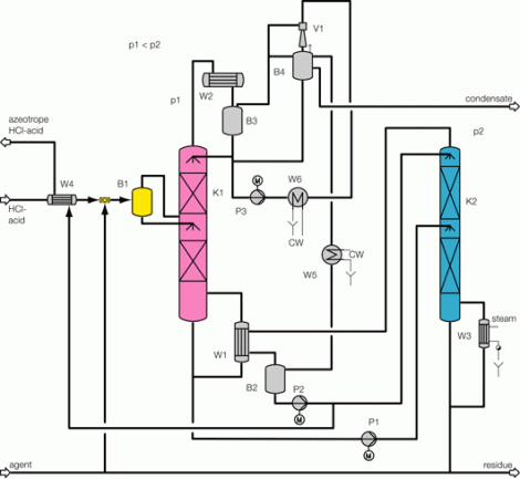
Illustr. 4: Combined technology for concentration of HCl

Combined technology for concentration of HCl

Process description combined technology for concentration

Illustration 4 above displays the flow chart of such a combined technology for the concentration of hydrochloric acid. The deployed raw acid is pre-heated in the feed pre-heater W4 against the concentrated hydrochloric acid; it is then mixed with the extractive agent, and then relaxed in the flash container B1. The resulting vapor is separated from the fluid in flash container B1, and feed into the middle of the vacuum column K1. The fluid from flash container B1 is also fed into the vacuum column K1 via an appropriate distributor. The mixture is rectified in vacuum column K1 so that water results in the column head and a mixture unfolds in the column bottom, whose composition almost matches to such found at a distillation borderline. This mixture is removed from the bottom of the vacuum column K1 via the pump P1, and fed into the pressure column K2.

The bottom mixture of the vacuum column is further rectified in the pressure column K2. A mixture now results as bottom product of pressure column K2 that matches to such found at the distillation borderline, and whose HCl concentration level is yet less than that of column K1 based on its system pressure. Thus, the bottom product of the pressure column K2 may therefore be recycled back to the column K1. For this, the bottom product of column K2 is relaxed in the flash container B1 together with the feed flow. As an extractive agent, the deployed ammonium chloride displays a high boiling point relative to the components of the feed acid; it then remains in the described fluid circulation. At the same time, employing ammonium chloride increases the relative volatility of HCl against water, so that the circulating volume of the described fluid circulation is minimized. In order to remove the contamination brought in by the feed flow, a partial flow is extracted from the bottom of the pressure column K2 and a specified amount of extractive agent is re-fed.

Concentrated hydrochloric acid of the desired concentration is produced at the head of the column K2. Vapor of the column K2 is condensed in the heat exchanger W1, which also serves as bottom heater of vacuum column K1. Achieving this heat integration minimizes energy deployment and thus operational costs of the plant. Hydrochloric acid of over-azeotrope concentration, which has condensed in heat exchanger W1, is collected in the distillation vessel B2, whereby a partial flow is re-fed to the top of pressure column K2 via hydrochloric acid pump P2. The main amount of the condensed hydrochloric acid is removed from distillation vessel B2 via the help of hydrochloric acid pump P2, and cooled down in feed pre-heater W4 against the feed flow, so that a cooled over-azeotrope hydrochloric acid flows as product from the concentration plant. Bottom heater W3, heated via saturated steam performs the heating of pressure column K2.

Generally, the above problem does not limit itself to sole absorption, extractive rectification, or cleaning of hydrochloric acid. Holistic solutions are frequently required, where an exhaust flow is cleaned while concentrated, cleaned hydrochloric acid is recycled.
Process Systems Questionnaire

Request More Information

Column Internals Questionnaire

Request a Quote

Want pricing? Have Questions?
We are here to help.