 It is generally known and accepted that to properly design a pneumatic conveying system, it is first necessary to determine certain properties and characteristics of the actual material to be conveyed, and ultimately conduct a pilot transfer test at the elevation and distance the customer wishes it to be conveyed to confirm if a desired transfer rate can be achieved.
In this post, we’ll discuss some of the basic material properties needed to help design a pneumatic conveying system that will meet a specific application’s requirements (note: this information is generally required by all system suppliers).
Bulk Density
Bulk density is the weight per unit volume (e.g. lbs. / ft3 or grams / cm3) of a material. However, it is important to differentiate between “loose” bulk density and “packed” bulk density. “Loose” material has generally not been de-aerated (i.e. gas removed from space between particles), compacted by gravity or settled by mechanical agitation, while “packed” material generally has been. “Loose” bulk density is typically used in pneumatic conveying calculations because most materials are conveyed in an aerated state (i.e., mixed with gas).
The bulk density can be measured by simply weighing a known volume of the aerated material.
It is important to note that transfer rates for most pneumatic conveying systems are expressed as a volumetric flow rate (e.g. ft3/ hr. or m3/ hr.). However, most process requirements are expressed as a mass flow rate (e.g. lbs./ hr. or kg/ hr.). The volumetric flow rate can be converted to an equivalent mass flow rate by simply multiplying the volumetric rate by the bulk density of the material. Please note, calculated rates are only theoretical and actual transfer rates should be determined by testing materials under simulated process conditions whenever possible.
Particle Size & Distribution (PSD)
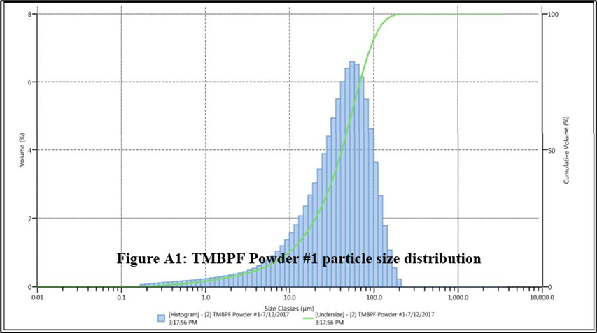
This material property describes the size variation between particles (typically measured in millimeters or microns) within a sample of material. Since all pneumatic conveying systems utilize filter media to separate the solids from the conveying gas, this property helps determine if a filter media will capture the smallest particles. High efficiency media typically requires more surface area and higher energy consumption to move the same amount of conveying gas through it.
In addition, a narrower particle size distribution helps improve the performance of almost all pneumatic conveying systems and is especially important when designing dense phase systems due to air-retention properties of consistently sized materials. Below is an example of a typical PSD diagram.

Angle of Repose, Angle of Slide & Cohesiveness
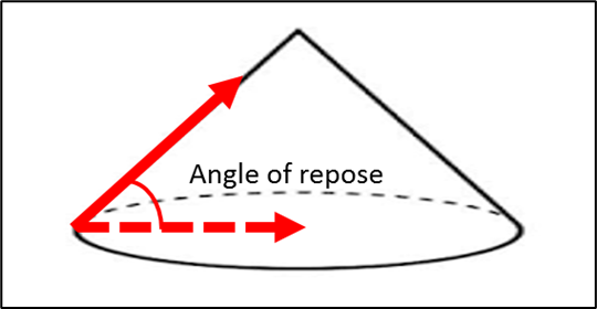
The “angle of repose” measures the steepness that a cone of material will form when poured onto a flat surface. Knowing this property is especially helpful when a fixed quantity of material is to be discharged into a container because the height of the resultant “cone” of the poured material can block the inlet port before the entire batch has been discharged into the vessel. To measure the angle of repose, product is poured onto a flat surface and the clearly defined angle is then measured with a protractor as illustrated in the diagram below:
Angle of Repose Guidelines
30° or less = very free flowing
30°-45° = free flowing
45°-60° = semi-free flowing
60° or more = non-free flowing
Products that achieve more than a 60° angle typically have a cohesive nature to them and will likely require vibration or aeration assistance to flatten out the top of a poured pile to make more efficient use of a fixed volume container.
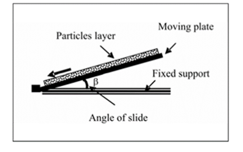
The “angle of slide” measures the angle of a surface at which material will begin to slide down under only the force of gravity. This property can be useful when evaluating the minimum angle that a hopper’s outlet cone should be to ensure material might flow out of it unassisted. However, there are other factors besides the friction between the material and the wall surface that will likely affect how well the material will flow.
One of these factors is the internal cohesive forces within the material caused by downward vertical force due to the weight of material above. This cohesive force can cause the material to bridge across a hopper’s outlet opening or form a vertical void space (known as a “rat hole”) above it.
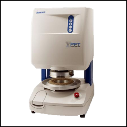
At De Dietrich Process Systems, we measure these internal forces using a Brookfield Powder Flow Tester (PFT) as shown below. This device provides the “Flow Factor” for the material (i.e. its level of cohesiveness), and recommends a hopper outlet diameter to prevent a bridge or rat hole from forming.
Minimum Ignition Energy (MIE), Kst and Pmax Values
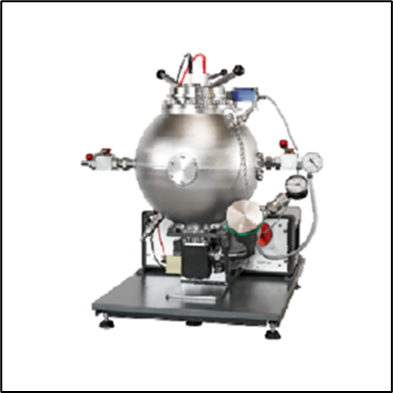
Minimum Ignition Energy is the amount of energy required to ignite a specific mixture of flammable material and oxygen, and Kst and Pmax are used to describe the severity of any resultant dust explosion. They are all measured using a standard ASTM procedure conducted using a test device like the one shown below.
Knowing the MIE of a material is especially useful when dealing with products that have a relatively low one (< 30 Kilojoules). When materials with a low MIE are pneumatically conveyed, additional precautions can be employed to help ensure the conditions necessary for the air/solids mixture to ignite are much less likely to result. These measures include using inert gas in the conveying stream and employing electrical ground monitoring systems.
The Kst of a material is the rate of pressure rise that occurs during an explosion and its Pmax is the maximum explosive pressure produced. The higher these values, the more severe an explosion will be. Knowing these values will help ensure 1) a system is designed such that an explosion is hopefully prevented from ever occurring, but if it does, 2) the equipment is designed to contain or safely vent the pressurized gas that results.
Material Transfer Testing
If a material is unfamiliar, or it is to be pneumatically conveyed farther or higher than ever previously done by a supplier, it should be transfer tested under those design conditions if at all possible. This will provide not only the expected transfer rate a customer can expect, but also reveal unexpected issues such as transfer line plugging, filter blinding, etc. Following review of a material’s Safety Data Sheet and acceptance for testing, material can typically be shipped to a supplier’s test facility in a drum, small bags or an FIBC (bulk bag). Customer’s are usually welcome to attend and observe transfer testing which can allow them to see what issues do arise and determine for themselves whether a specific type of pneumatic conveying system will be appropriate for their intended use.
Summary
Knowing the properties of your powder can provide key insights for transfer optimization. Whether already known by the customer or determined by the vendor, this data is usually required to ensure the testing environment is safe for test personnel and customers who wish to attend.
De Dietrich Process Systems provides powder handling solutions to carry out a wide range of containment and transfer applications. The Powder Pump is at the heart of our systems, and provides safe, reliable and efficient material conveying. Coupled with our in-house testing capabilities, DDPS can provide a process guarantee that we can move your powder from where it is to where you want it to be.
For more information about our solids testing capabilities click here.
Interested in learning more about bulk solids testing? Watch our on-demand webinar.